Using AutoCAD, I had to create three 3D drawings from a range of different disciplines. This drawings would then also have to be presented in a 2D format showing different elevation and orthographic perspectives using hidden line, wireframe and rendered styles.
The disciplines for this exercise were: mechanical; architectural; piping; electrical; instrument; product; engineering; civil; structural; landscape; interior and packaging. After coming up with a number of ideas which I discussed with friends and family, my chosen three designs were a road drain, a straight pipe and a plug.
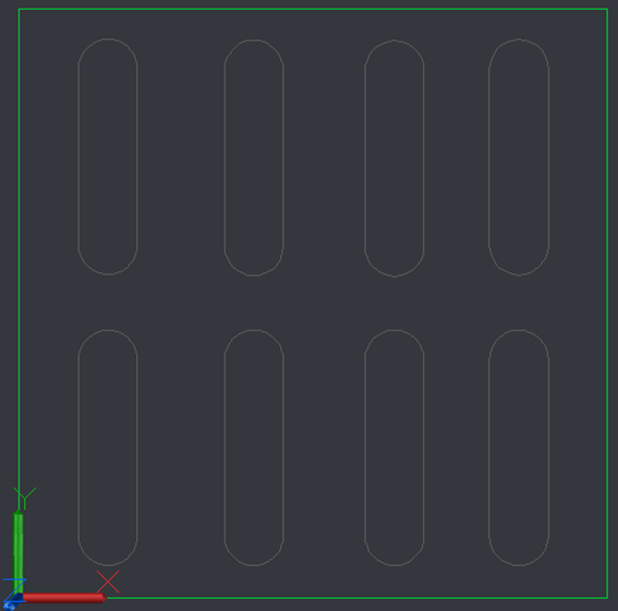
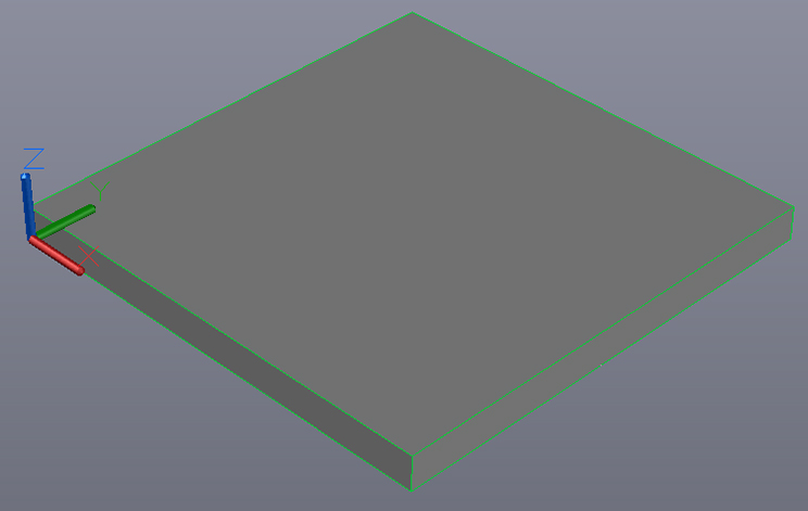
The first model I created was the road drain. I started the 2D design.
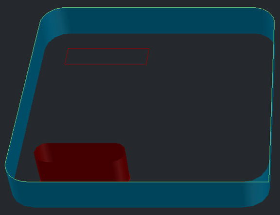
During the 3D design for the road drain I began by placing a planar surface to the sides. However, this was not successful as when I added fillets to the corners the new planars did not register the corner curves and resulted in it staying square. Another issue I encountered was the use of the loft on the slots. This was based on me completing this in the wrong order.
Based on my initial problems I went back to the 2D design staged and began the 3D process again using straight corners instead of curved. This enabled me to produce the full 3D model.
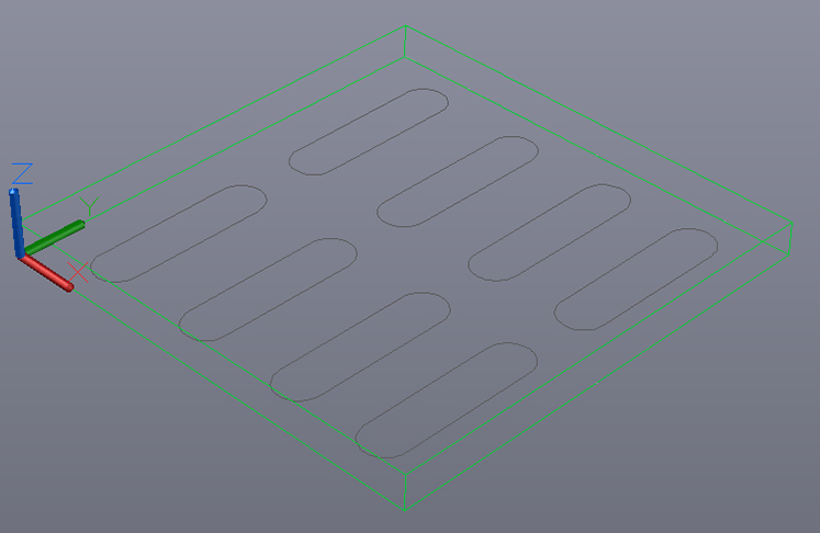
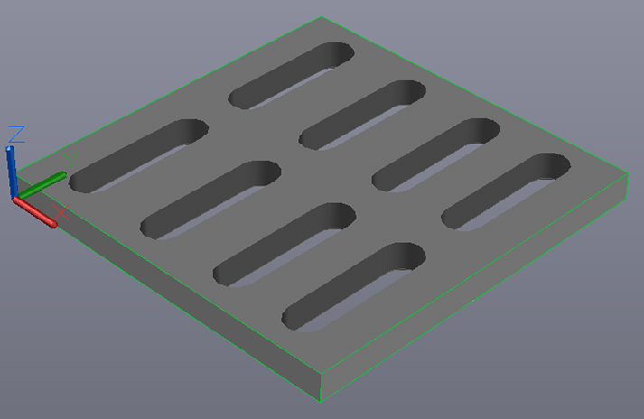
Once the initial design was completed, I placed the planar surface on the faces.
The final phase of the design was to add the gaps within the drain. I completed this using loft.
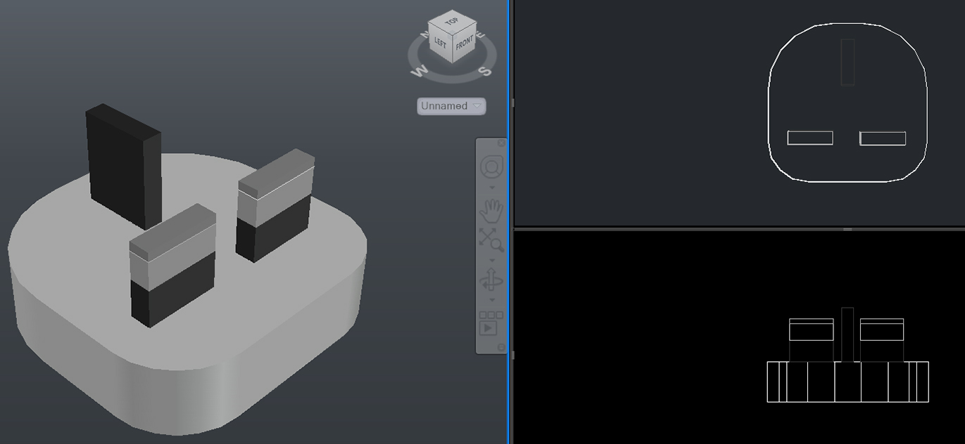
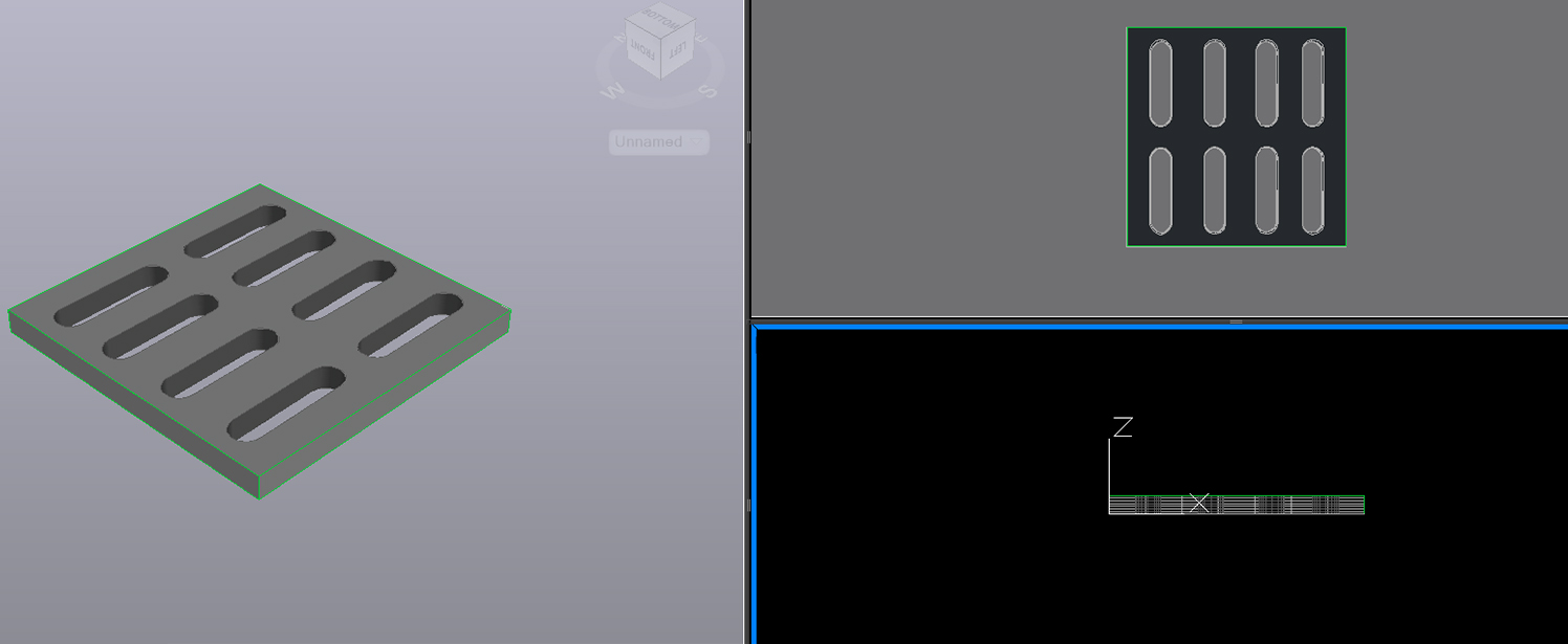
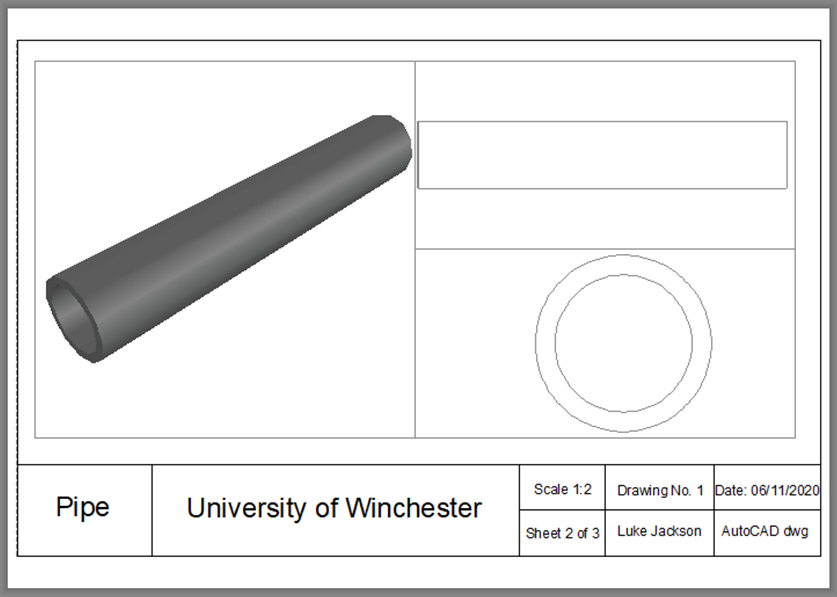
Once the design was finished, I created viewports to show different elevations and visual styles of the model.
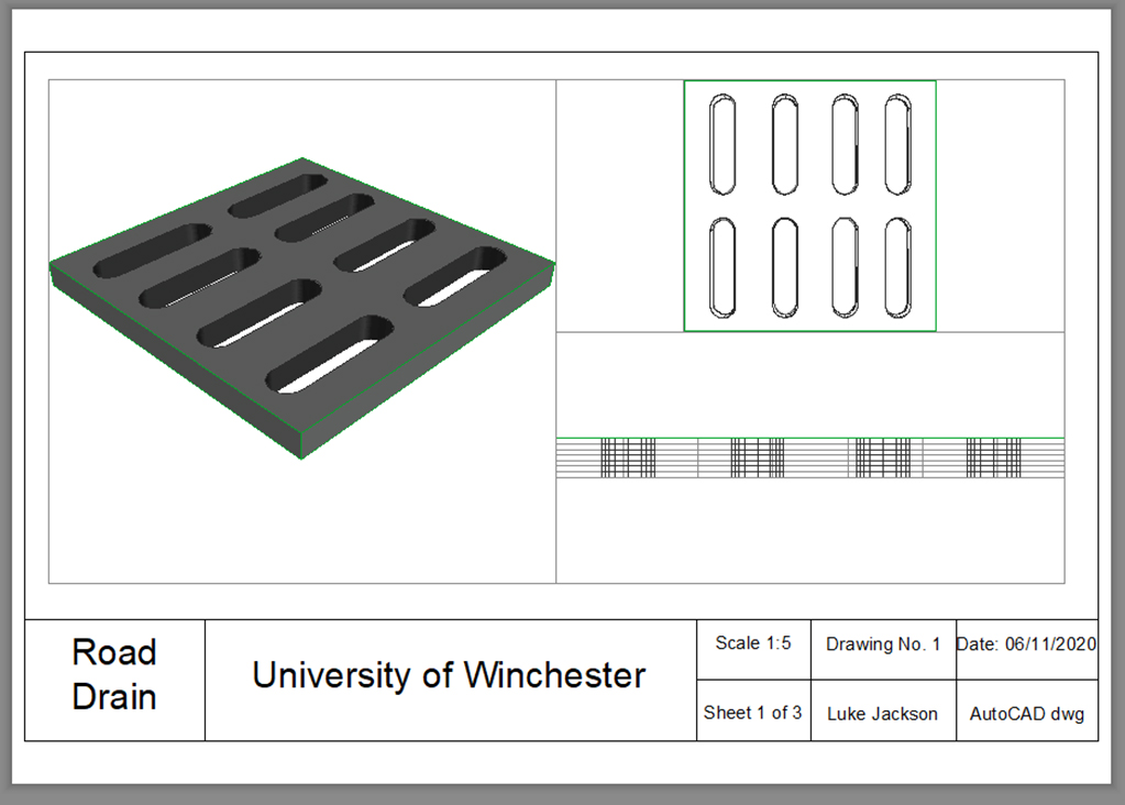
Finally, I had to put the viewports onto a template. this completed the model.
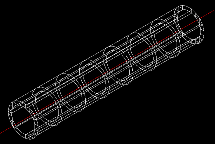
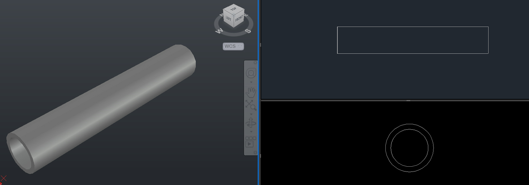
My second design was of a pipe. I followed the same 2D style format, the viewport and template as I did for the road drain. However, for the 3D model I used revolve with a guideline to rotate on. These are shown in the diagrams below.

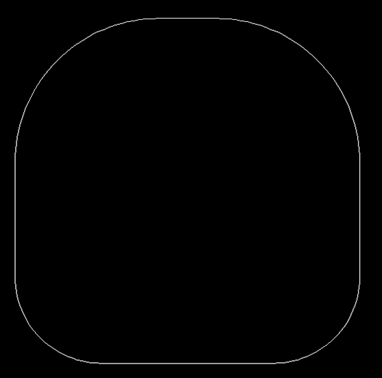
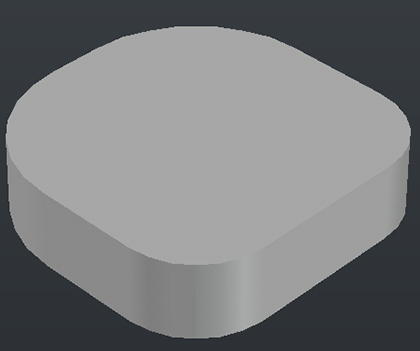
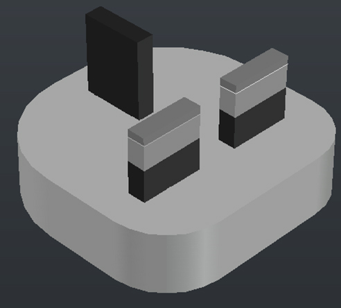
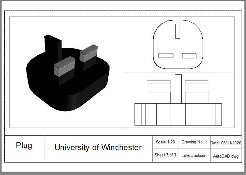
For the electric plug design I followed the same processes as the other two. However, for the 3D model I used extrude I incorporated into the model. The diagrams below show some of the processes and layers I used.