This Project was to create a prototype for either a mobile, portable, wearable or integrated device which also had to incorparate a visual or physical interface that would help the user and will include an interface design. The context to choose ranged from travelling on public transport to a technology-based children's toy. Our group chose a haptic feedback sensor that could be used to help those during archery that were visually impaired. The sensor would be attached to their bow. Because of what we were working on, we decided to call our group "Aimed". As I am studying CAD, my role within the project was to create sketches, 2D designs and 3D models of the device.
The initial concept was provided by the groups designer. The idea behind this device was to help those with visual and/or hearing impairment to be able to do archery. Figure 1 shows the initial idea.
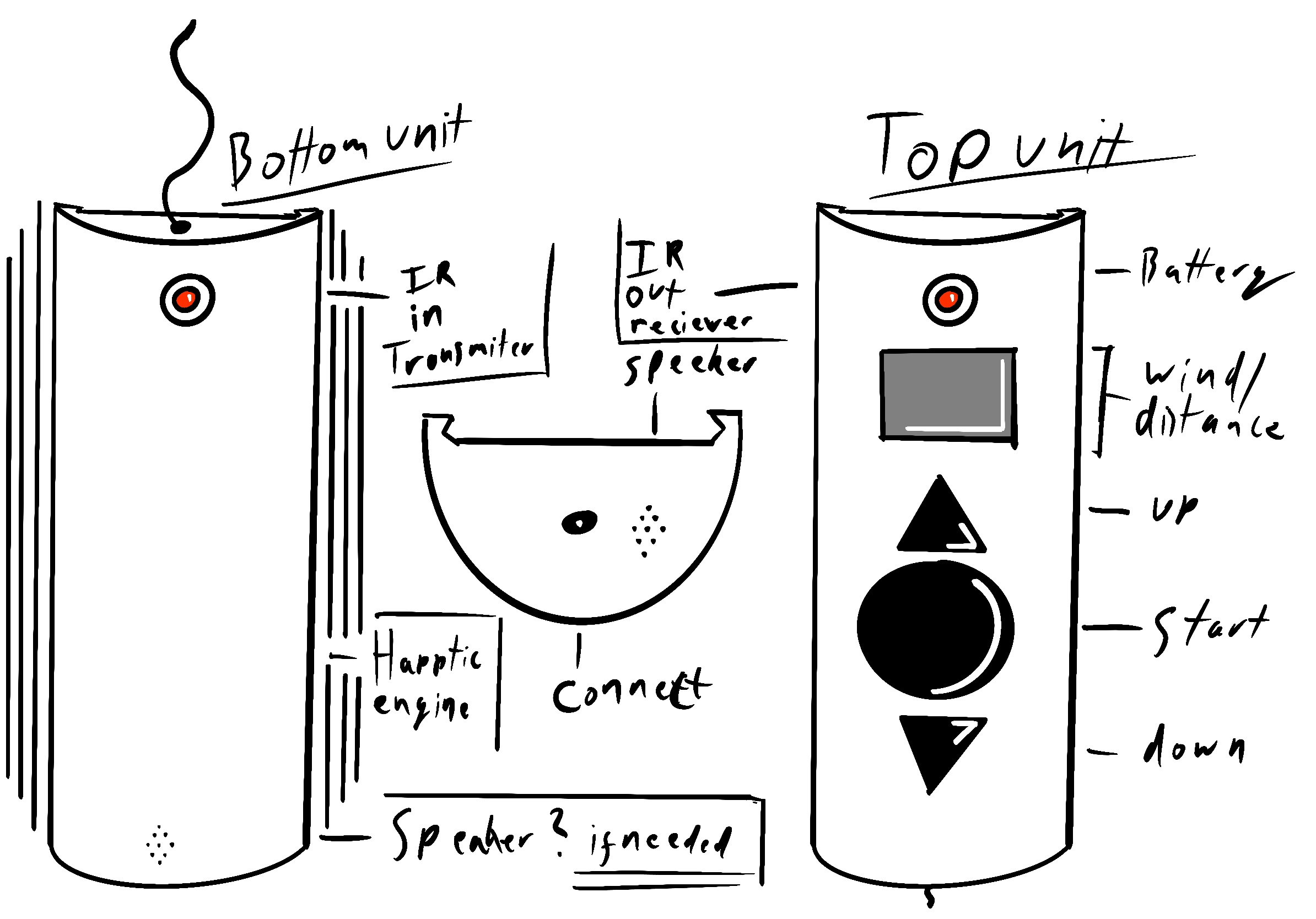
fig.1 - Concept Idea
I discussed with the designer the overall dimensions for the product. From this, I produced the sketches (fig.2) and the 2D design (fig.3). From this I then started work on the 3D model (fig.4). It was during this I realised that the design would only fit one size of bow and so I stopped working on the 3D work. I then began to look at ways to overcome this to enable it to fit various sizes of bow and how this would attach/grip.
.jpg)
fig.2 - Initital Sketch
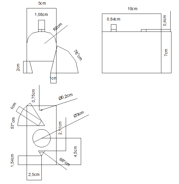
fig.3 - 2D Design
.jpg)
fig.4 - 3D Model
Looking at the issues regarding the grip, I found inspiration from an adjustable spring holder that I use while painting warhammer figures as a hobby (fig.5). This piece holds the plastic base of the figures in place as you apply the paint to the model. This was discussed within the team and once we had agreement I then updated my initial sketch (fig.6), the 2D design (fig.7) and the 3D model (fig.8). As the design progressed, there would be the need to revisit the design again.
.jpg)
fig.5 - Inspiration
.jpg)
fig.6 - Second Sketch
2ddesigns.jpg)
fig.7 - 2D Design

fig.8 - 3D Model
Further modifications were made where by I made the overall piece curved to give it a smoother feel. I also looked to add rubber to the grip which would make it more stable when attached to the bow. This would also pervent it from scratching or damaging the bow. I then updated my sketch (fig.9) and 3D model to reflect these changes (fig.10 and 11).
.jpg)
fig.9 - Third Sketch
model1.jpg)
fig.10 - Corner View
model2.jpg)
fig.11 -Top View
During further development I found that the model would not have the required space for the electronics that were needed for the sensor or for the on/off function. I rectified this and I also realised that the grip I had designed needed to be ammended to enable somebody to be able to open and close the grips. I looked at different options for this as shown in the sketch (fig.12) and also in the 3D models (figures 13 to 15)
.jpg)
fig.12 - Fourth Sketch
model1.jpg)
fig.13 - Corner View
model2.jpg)
fig.14 - Top View
model3.jpg)
fig.15 - Side View
Towards the end of my involvement within this project, I came up with a final solution to operate the grips which I believe would make this more user friendly. This would be my final version. The following show the final sketch, 2D design and 3D model.
Fig.16 shows the final Sketch:
.jpg)
fig.16 - Final Sketch
Fig.17 shows the final 2D Design:
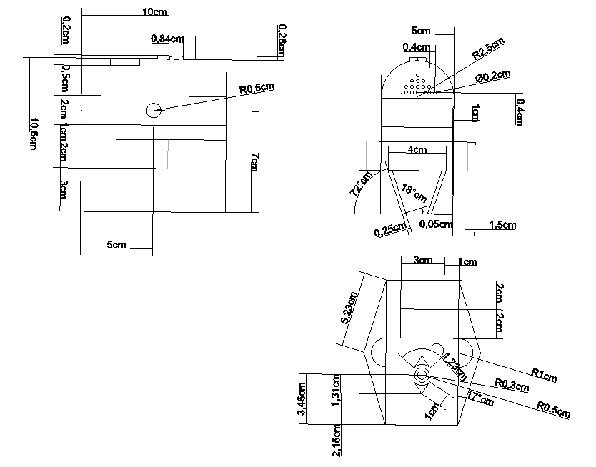
fig.17 - 2D Design
Figures 18 to 22 shows the final 3D design:
image1of5.jpg)
fig.18 - Side View
image2of5.jpg)
fig.19 - Corner View
image3of5.jpg)
fig.20 -Top View
image4of5.jpg)
fig.21 - Bottom View
image5of5.jpg)
fig.22 - Back View
The following are animations I have created to show the completed model:
Fig.23 shows the rendered version of the model.
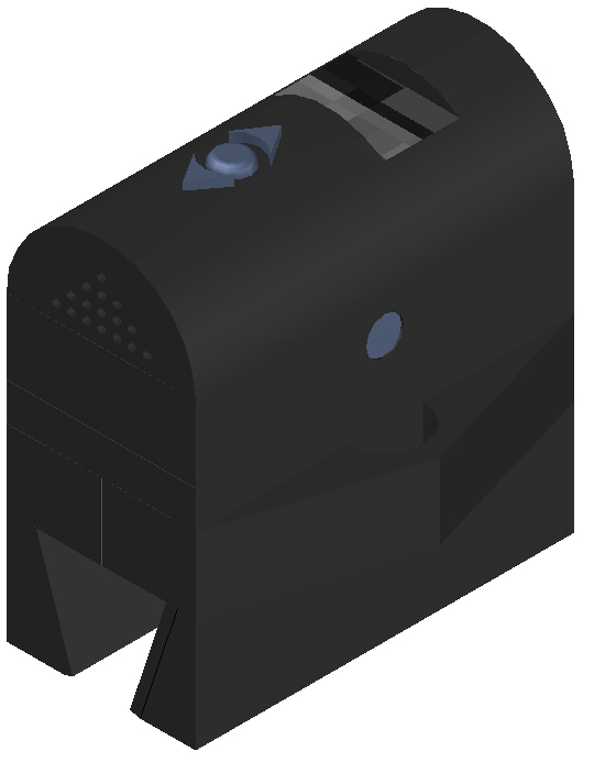
fig.23 - Rendered Model
Fig.24 shows the mechianism I created for the grip:
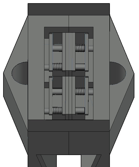
fig.24 - Mechianism
Fig.25 is the exploded view for the completed device:
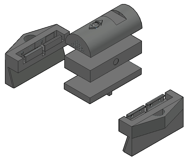
fig.25 - Exploded View
Fig.26 shows the different designs during the course of the project:
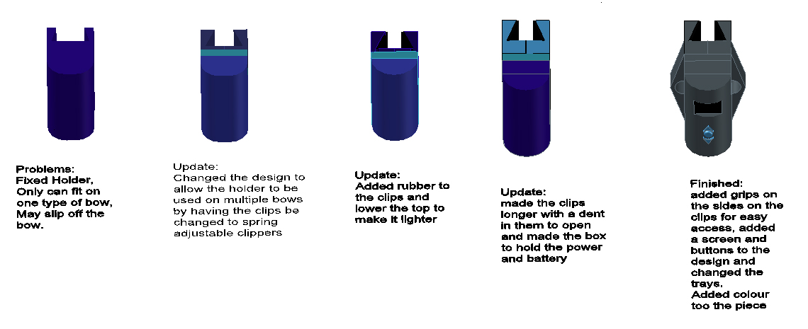
fig.26 - Design Journey
These final diagrams, Fig 27 to 29, show my workings out and documents that I used when I designed how the grip would work and used the following to determine how much strength the individual would need to open the grip. I expanded on this within exercise one of the ergonomics:
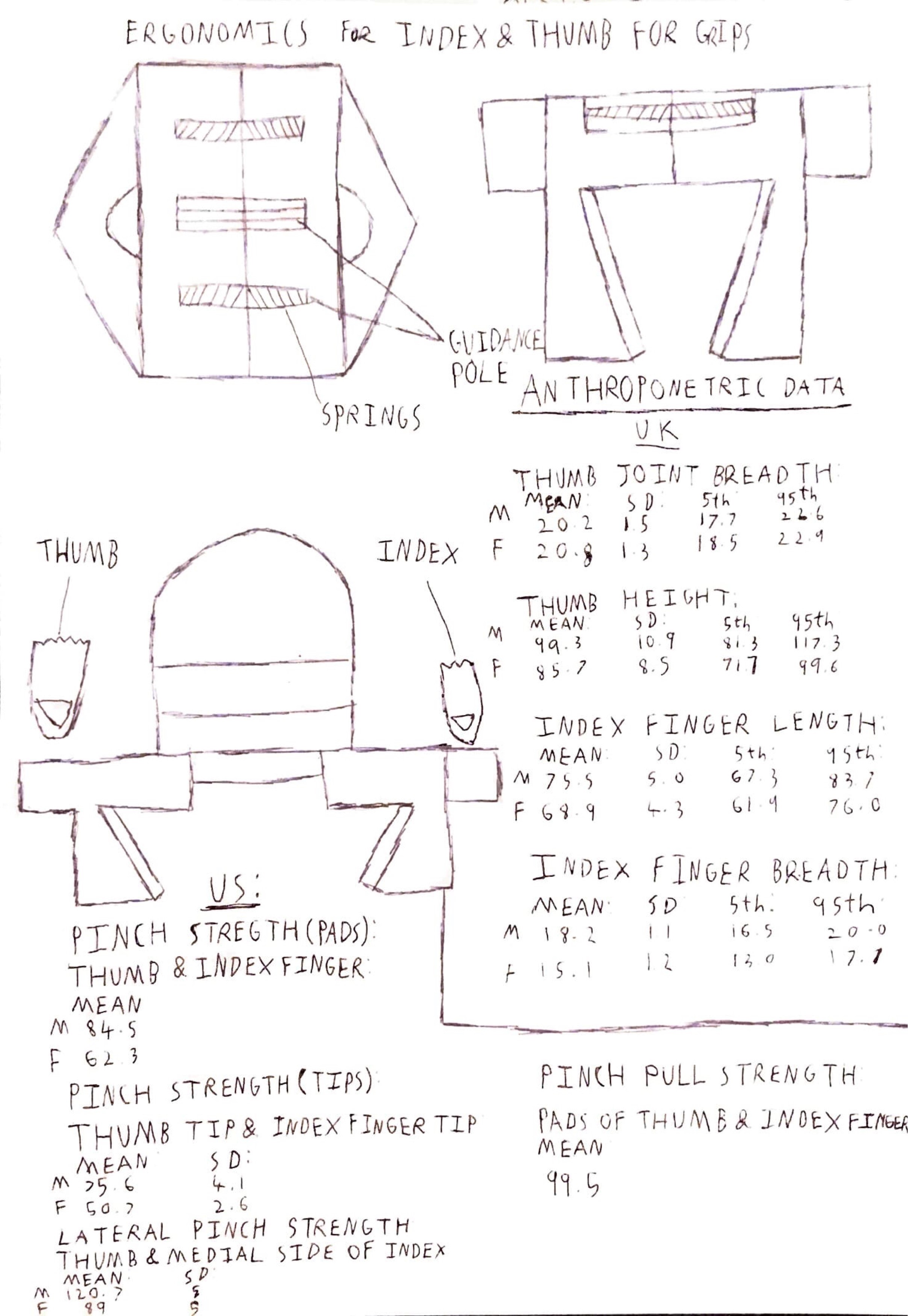
fig.27 - Anthropomtic Data Sketch
.jpg)
fig.28 - Example One
.jpg)
fig.29 - Example Two